|
本文详细介绍了差分信号的各种特性,从原理,PCB设计,仿真等各方面阐述了差分信号的特点,为intel内部培训资料,不可多得,值得参考,强烈推荐,以下为资料主要内容:
Differential Signaling Introduction
Reading Chapter 6
Agenda
1、Differential Signaling Definition
2、Voltage Parameters
3、Common mode parameters
4、Differential mode parameters
5、Current mode logic (CML) buffer
6、Relate to parameters
7、Modeling & simulation
8、Timing parameters
9、Clock recovery
10、Embedded clock
11、AC coupling
12、Common mode response
13、Issues with simulation
14、8B10B encoding
15、DC balanced codes
16、Duty Cycle distortion
17、Cycle
Single Ended Signaling
All electrical signal circuits require a loop or return path.
Single ended signal subject several means of distortions and noise.
Ground or reference may move due to switching currents (SSO noise). We touched on this in the ground onundrum class.
A single ended receiver only cares about a voltage that is referenced to its own ground.
Electromagnetic interference can impose voltage on a single ended signal.
Signal passing from one board to another are subject to the local ground disturbance.
We can counteract many of these effect by adding more ground.
As frequencies increase beyond 1GHz, 80% of the signal will be lost.
Review of threshold sensitivity
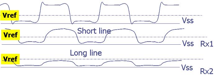
The wave is referenced to either Vcc or Vss. Consequently the effective DC value of the wave will be tied to one of these rails.
The wave is attenuated around the effective DC component of the waveform, but the reference does not change accordingly. Hence the clock trigger point between various clock load points is very sensitive to distortion and attenuation.
Differential Signaling
Any signal can be considered a loop is completed by two wires.
One of the “wires” in single ended signaling is the “ground plane”
Differential signaling uses two conductors
The transmitter translates the single input signal into a pair of outputs that are driven 180° out of phase.
The receiver, a differential amplifier, recovers the signal as the difference in the voltages on the two lines.
Advantages of differential signaling can be summed up as follows
Differential Signaling is not sensitive to SSO noise.
A differential receiver is tolerant of its ground moving around.
If each “wire” of pair is on close proximity of one and other. electromagnetic interference imposes the same voltage on both signals. The difference cancels out the effect.
Since the AC currents in the “wires” are equal but opposite and proximal, radiated EMI is reduced.
Signals passing from one board to another are not subject to the local ground disturbances.
As frequencies increase beyond 1GHz, up to 80% of the signal may be lost, but difference still crosses 0 volts.
There are still loss issues for differential signaling but only come into play in high loss system. Most single ended systems assume approximately 15% channel loss.
The cost is doubling the signal wires, but this may not be so bad as compared to adding grounds to improve single ended signaling.
Routing constraint: Pair signals need to be routed together.
Differential signal have certain symmetry requirements that may pose routing challenges.
Differential Signal Parameters
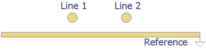
Voltage on line 1 = a
Voltage on line 2 = b
Differential voltage d = a-b
Common mode voltage c= (a+b)/2
Odd mode signal, o = (a-b)/2
Even mode signal, e = (a+b)/2
Signal on line 1 a = e+o
Signal on line 2 b = e-o
Useful relations; o = b/2; e = c
Propagation Terms to Consider
Differential mode propagation
Common mode propagation
Single ended mode (uncoupled) propagation
This is when the other line is not driven but terminated to absorbed reflections.
Transmission line matrixes will reflect these modes.
……………………
……………………
具体请下载参考:
差分信号(collected by 19245068).ppt
|