 List of CAUTION/ WARNING DANGER LABELS.........................................................L-1 1 External View ................................................................................................................1-1/3 1.1 Appearance .................................................................................................................................1-1/3 1.2 Main Components .......................................................................................................................1-3/3 2 Pre-Operation Check .....................................................................................................2-1/2 2.1 Preparations ...............................................................................................................................2-1/2 2.2 Checking Items...........................................................................................................................2-1/2 2.3 Main Circuit Breaker Specifications ..........................................................................................2-2/2 3 Parts Replacement Procedure ......................................................................................3-1/3 3.1 Replacement of Fan Motor..........................................................................................................3-1/3 3.1.1 Replacement of Control Rack Fan Motor............................................................................3-2/3 3.1.2 Replacement of Prober Main Body Fan Motor ...................................................................3-3/3 4 Adjustment...................................................................................................................4-1/22 4.1 Adjustment of Servo Driver ......................................................................................................4-1/22 4.2 Adjustment of Displacement Sensor ......................................................................................4-15/22 4.3 Adjustment of Wafer Sensor...................................................................................................4-17/22 4.4 Adjustment of Overhang Sensor.............................................................................................4-18/22 4.5 Adjustment of Wafer Center Sensors .....................................................................................4-20/23 4.6 Adjustment of LCD display condition ....................................................................................4-22/22 5 Electrical Units...........................................................................................................................5-1/24 5.1 Electrical Units Location ..........................................................................................................5-1/24 5.2 Machine Rear ............................................................................................................................5-2/24 5.3 Location Inside the Control Rack .............................................................................................5-3/24 5.4 Loader Electrical Components..................................................................................................5-4/24 5.4.1 Loader Board / Motor Drivers............................................................................................5-4/24 5.4.2 5AX DRV (FA0138B)SW1..................................................................................................5-5/24 5.5 VME RACK Board Location......................................................................................................5-6/24 5.6 Power Supply............................................................................................................................5-7/24 5.7 Fuses .........................................................................................................................................5-9/24 5.8 Display Unit............................................................................................................................5-10/24 5.9 Specifications of LCD Display.................................................................................................5-11/24 5.10 CCD CAMERA.......................................................................................................................5-13/24 5.11 FDD, HDD and MOD ............................................................................................................5-14/24 5.12 Thermal Printer ....................................................................................................................5-15/24 5.13 Heat-Up Unit.........................................................................................................................5-19/24 5.14 Temperature Controller ........................................................................................................5-22/24 6 Safety Measures.............................................................................................................6-1/6 6.1 EMO ( EMERGENCY POWER OFF )........................................................................................6-1/6 6.2 Interlock Configuration...............................................................................................................6-4/6 6.3 Lockout Device Setting (Lock out Configuration)......................................................................6-6/6 7 Maintenance Parts List.................................................................................................7-1/6 7.1 Rank A Parts ...............................................................................................................................7-1/6 7.2 Rank B Parts ...............................................................................................................................7-2/6 7.3 Rank C Parts ...............................................................................................................................7-3/6 7.4 Rank C Parts – Boards................................................................................................................7-5/6 7.5 Rank C Parts – Option Boards ...................................................................................................7-6/6 8 Troubleshooting ...........................................................................................................8-1/25 9 Troubleshooting Flowchart ...........................................................................................9-1/3 10 Circuit Diagrams ..................................................................................................... 10-1/35  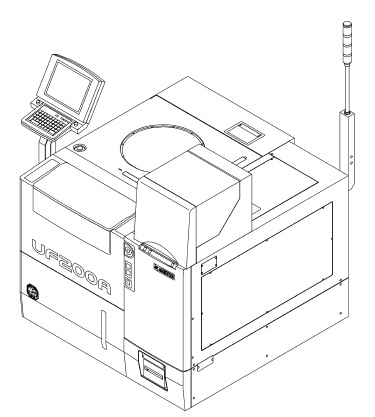  通过以上介绍,您应该已经清楚本资料的大概内容,详情请下载参考:UF190B-200A maintenance manual |